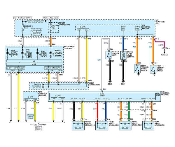
 Kia Optima: Circuit Diagram - ESC (1)

See also:
Installation
1.
Install the fob holder.
2.
Install the glove box.
...
Inspection
Connecting Rod
1.
Check the connecting rod end
play.Using a feeler gauge, measure the end play while moving the connecting
rod back and forth.
End play :Standard : 0.10~ ...
Heated Oxygen Sensor (HO2S). Description and Operation
Description
Heated Oxygen Sensor (HO2S) consists of zirconium and alumina
and is installed both upstream and downstream of the Manifold Catalytic Converter.
The sensor output voltage varies in ...
Copyright © www.kiopman.com 2024


