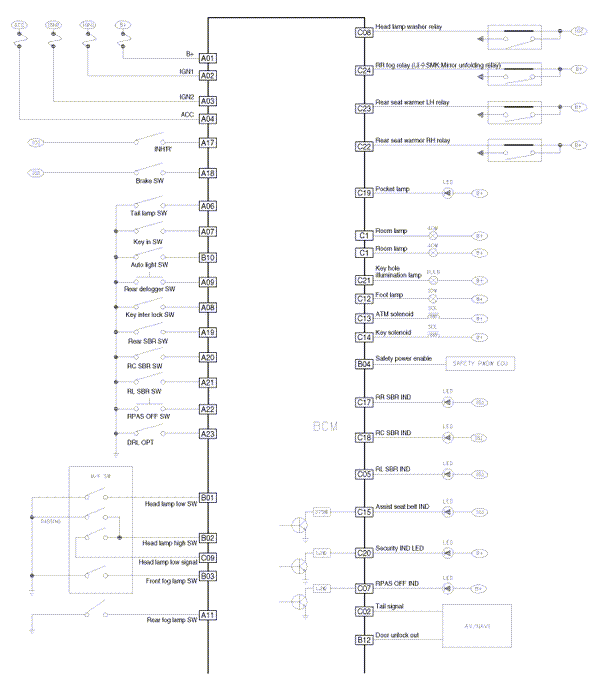
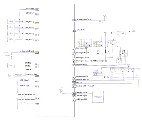
 Kia Optima: Circuit Diagram


 BCM Connector Terminals
BCM Input Signal SPEC
Signal Name
Description
Input Characteristics
(determinant condition
of connector base)
Power
Source
(Pull Up)
...
See also:
Circuit Diagram
...
Inspection
1.
Turn ignition switch OFF.
2.
Disconnect the oil temperature
sensor connector.
3.
Measure resistance between sensor
signal terminal and sensor g ...
Fan Speed Control Knob
The fan speed control knob is the knob closest to the driver. Four (4) adjustable
fan speeds are provided which increase as the number increases. The ignition switch
must be in the ON position for ...
Copyright © www.kiopman.com 2024

