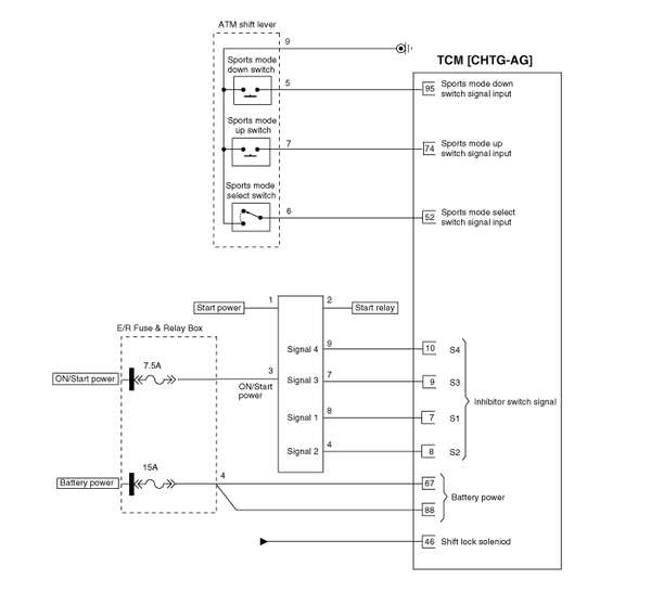
 Kia Optima: Circuit Diagram


 TCM Terminal Input/ Output Signal
Connector [CHTG-AG]
Pin
Description
Condition
Input/output value
Type
Level
1
-
...
See also:
Components and Components Location
Component Location
1. Windshield wiper arm & blade
2. Wiper & washer switch
3. Windshield washer hose
4. Windshield wiper motor & linkage
5. Washer mo ...
Front Hub / Knuckle. Components and Components Location
Components
1. Driveshaft nut
2. Brake disc
3. Hub
4. Wheel bearing
5. Snap ring
6. Dust cover
7. Knuckle
8. Driveshaft
...
Component location
1. Driveshaft (LH)
2. Driveshaft (RH)
1. Driveshaft (LH)
2. Circlip
3. Inner shaft bearing bracket assembly
4. Circlip
5. Driv ...
Copyright © www.kiopman.com 2024

