Kia Optima manuals
For much of its life, the Kia Optima has been firmly pegged as an also-ran vehicle. Introduced as Kia's first midsize sedan, the first-generation Optima couldn't promise the refinement, documented reliability and assured resale value of its key Japanese competitors. The second-generation Kia Optima followed much the same playbook, though with considerably better results.
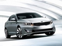
Kia's latest, third-generation Optima is an also-ran no longer. With sleek styling, plenty of standard features, potent engine choices and substantial value, the current Optima is a top pick for a midsize family sedan.
The current Kia Optima is very similar to the Hyundai Sonata, but to Kia's credit, the Optima has a distinctive European flair to it. From the outside and inside, the Optima looks and feels like a much more expensive car than its humble price tag would suggest.